Cracking and chipping of header punches are rarely caused by “bad steel” alone; they are often the result of poor stress distribution. In high-load cold heading, adjusting punch geometry—specifically optimizing chamfers, transition radii, and head profiles—is the most effective way to eliminate localized stress concentrations. By redesigning the tool to distribute impact forces evenly, manufacturers can prevent immediate fractures and extend tool life by 1.5 to 2 times.
The Engineering Behind the Shape
When a punch fails after only a few thousand cycles, the instinct is often to upgrade to a harder material. However, if the geometry is flawed, a harder material (like Carbide) will simply shatter faster. At Xiluo Mold Technology, we treat punch failure as a physics problem first and a material problem second.
Here is how we solve premature failure by engineering the shape of the tool.
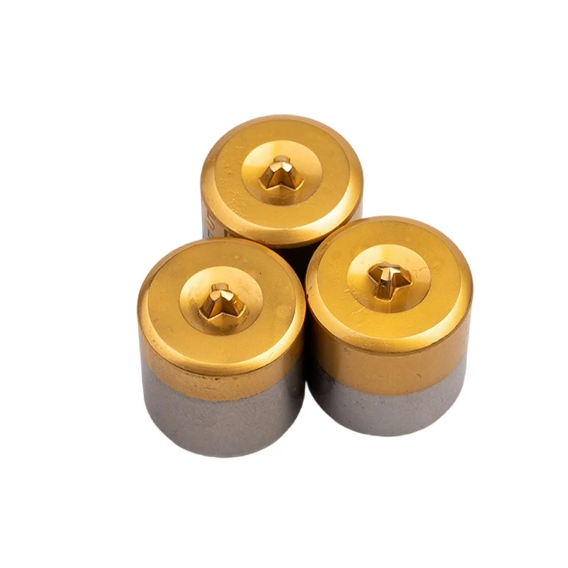
Table of Contents
- The Physics of Stress Concentration and Failure
- Critical Modifications: Chamfers and Transition Radii
- Matching Material Hardness to Geometric Design
- Case Study: Optimizing Head Profiles for Screw Production
- Case Study: Stabilizing Carbide with Side-Wall Curvature
- The Synergy of Geometry and Surface Coatings
- Leveraging Inventory for Rapid Geometric Testing
1. The Physics of Stress Concentration and Failure
Why do punches crack in the same spot every time?
Failures are almost always caused by stress risers—points where the geometric shape causes the load to multiply locally. In high-volume cold heading, a sharp corner or an abrupt transition acts as a focal point for shock waves. Adjusting punch geometry to smooth these transitions allows the shock to dissipate through the body of the tool rather than accumulating at a single “weak point,” preventing the initiation of micro-cracks.
Understanding the Load Path
When the ram hits the wire, the force seeks the path of least resistance.
- Sharp Corners: Create a “notch effect,” raising local stress by 300% or more.
- Smooth Radii: Distribute the compressive load over a wider surface area.
- Result: A tool with optimized geometry can handle higher tonnage than a standard tool, even if they are made of the exact same steel.
2. Critical Modifications: Chamfers and Transition Radii
What are the specific geometric changes that reduce chipping?
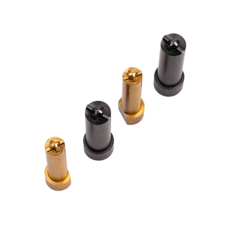
The most impactful adjustments are the introduction of calculated chamfers and blended radii at the impact edge. A sharp 90-degree edge is prone to immediate chipping (spalling). By adjusting punch geometry to include a specific angle chamfer or a logarithmic curve, we shift the contact point away from the brittle edge, directing the force toward the solid core of the punch where the material is strongest.
Practical Design Adjustments
We recommend specific geometric tweaks based on the failure mode:
| Failure Mode | Geometric Solution | Mechanism |
| Edge Chipping | Increase Chamfer Angle | Moves impact zone away from the fragile periphery. |
| Transverse Cracking | Larger Transition Radius | Reduces the “notch effect” between the head and shank. |
| Top Deformation | Flatness/Concavity Adjustment | Ensures the wire is trapped before full compression. |
3. Matching Material Hardness to Geometric Design
How does geometry influence the choice of material?
Harder materials require more forgiving geometry. A Tungsten Carbide punch (Hardness: Rockwell C60–65) offers incredible wear resistance but has low tensile strength. If the geometry includes sharp corners, the carbide will snap. By adjusting punch geometry to eliminate stress risers, we enable the use of these ultra-hard materials in high-impact applications, combining the toughness of the design with the wear resistance of the material.
The Hardness Spectrum
- Standard Tool Steel (HRC 50–55): Can tolerate sharper corners due to higher elasticity.
- Tungsten Carbide (HRC 60–65): Requires large radii and smooth transitions.
- Engineering Rule: The harder the material, the “softer” the geometry must be. We often see clients fail because they copy a steel design directly into carbide without adjusting the shape.
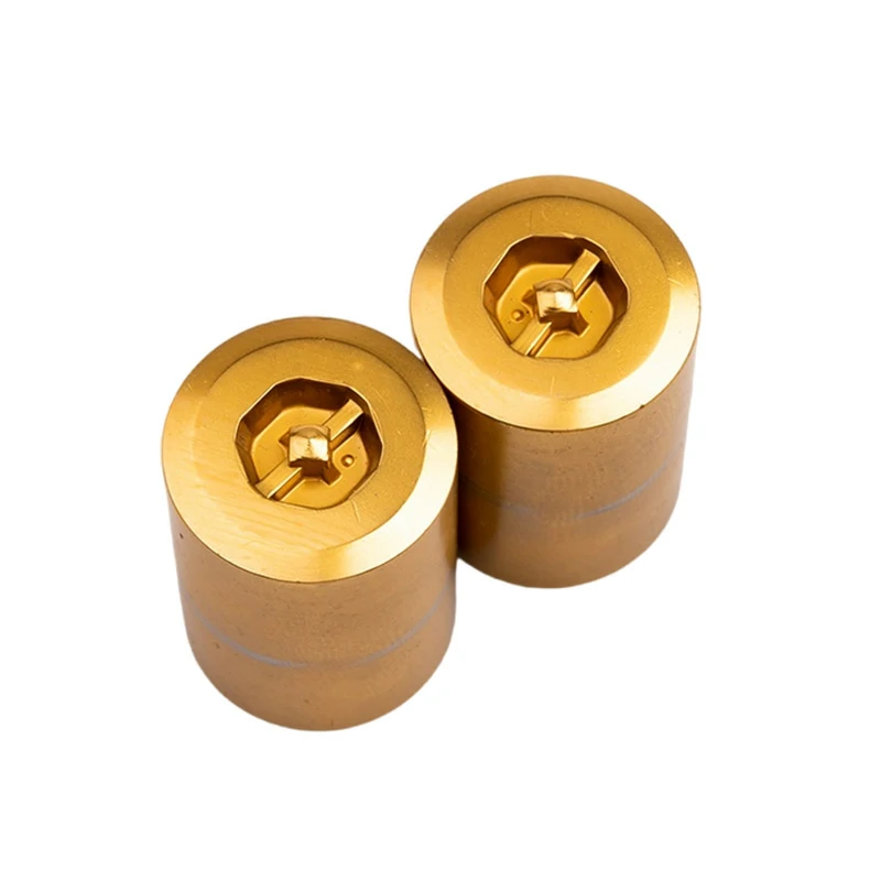
4. Case Study: Optimizing Head Profiles for Screw Production
Can a simple shape change double the life of a tool?
Yes. In a recent project for a high-speed screw production line, the client was experiencing vertical cracking on the punch face. We analyzed the failure and found the load was concentrated on the outer rim. By adjusting punch geometry—specifically optimizing the head profile and blending the transition curve—we redistributed the load. The result was a 1.5x increase in continuous run time and a near-total elimination of micro-cracking.
Project Details
- Issue: Cracks developing after 20,000 cycles.
- Adjustment: Redesigned the “land” area and introduced a double-angle chamfer.
- Outcome: The optimized punch now runs for 35,000+ cycles. The smooth transition prevented the stress accumulation that was splitting the tool.
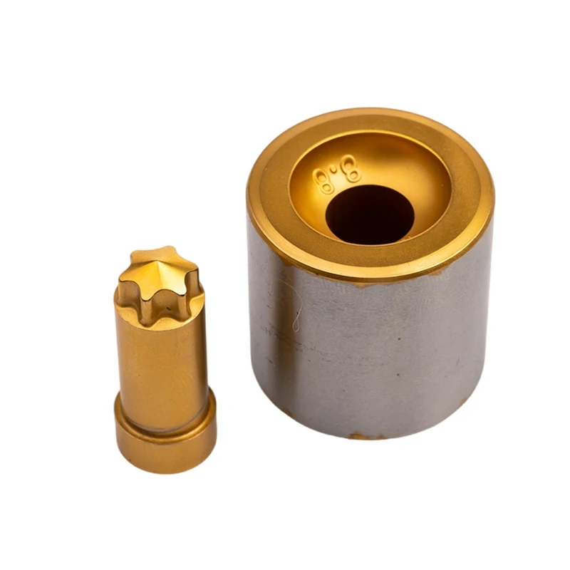
5. Case Study: Stabilizing Carbide with Side-Wall Curvature
How do you stop carbide punches from shattering in high-volume lines?
In a separate case for an automotive fastener manufacturer, the client wanted to use Carbide for longevity but faced catastrophic shattering. We focused on adjusting punch geometry along the side-walls (the curvature leading to the shank). By experimenting with different sidewall curvatures, we found a “sweet spot” that supported the carbide structure better under load.
Results of the Geometric Overhaul
- Material: Tungsten Carbide with Cobalt binder.
- Change: Modified sidewall radius to reduce vibration/harmonics.
- Impact: The new design stabilized the production line. Downtime frequency dropped, and the “shattering” issue was resolved, proving that carbide is viable if the shape is right.
6. The Synergy of Geometry and Surface Coatings
Does geometry eliminate the need for coatings?
No, they work together. Geometry handles the structural load; coatings handle the surface friction. In high-pressure applications, we found that adjusting punch geometry to reduce localized pressure points enhances the effectiveness of coatings like TiN or TiAlN. When the load is spread evenly, the coating doesn’t strip off prematurely, further preventing surface micro-cracks caused by heat accumulation.
The Multiplier Effect
In a high-pressure workshop test:
- Geometry Optimization: Reduced structural stress.
- Surface Treatment (TiAlN): Reduced friction heat.
- Result: The combined approach reduced the scrap rate significantly. The tool stayed cool and intact, as the geometry prevented cracking while the coating prevented wear.
7. Leveraging Inventory for Rapid Geometric Testing
How can manufacturers test these designs without long lead times?
The key is access to a wide range of standard blanks that can be modified quickly. At Xiluo, we maintain an inventory of approximately 200,000 standard punches. This allows us to pull a standard blank and grind a custom geometry for testing within days, rather than weeks. This capability is crucial for “A/B testing” different geometric angles to find the perfect solution for a specific production line.
Conclusion
If your punches are cracking, stop looking at the steel grade and start looking at the blueprint. The solution lies in physics. By adjusting punch geometry—smoothing radii, optimizing chamfers, and balancing the load—you can safely use harder materials (HRC 50-65) and advanced coatings to achieve record-breaking tool life.
At Xiluo Mold Technology Co., Ltd, we don’t just manufacture to print; we review the design to ensure it can survive the reality of your factory floor.
Experiencing premature tool breakage? Contact our engineering team today for a geometric stress analysis.